TECHNOLOGY
Brazed joints
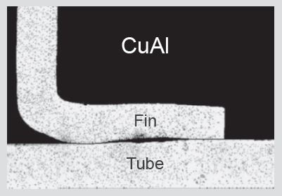
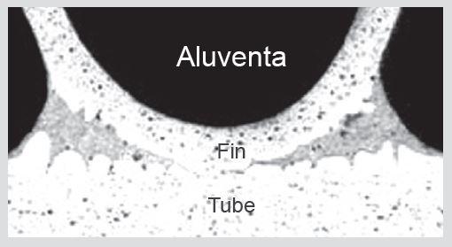
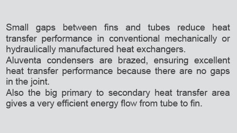
Poor contact between fins and tubes accounts for 5-10% of heat transfer resistance in a conventional mechanical manufactured Fin and tube heat exchanger.
The resistance increases during service period due to fouling in the gap. The all aluminium condenser is brazed.
The metallurgical bond between fins and tubes gives a joint with optimum conduct of heat.
Tube design
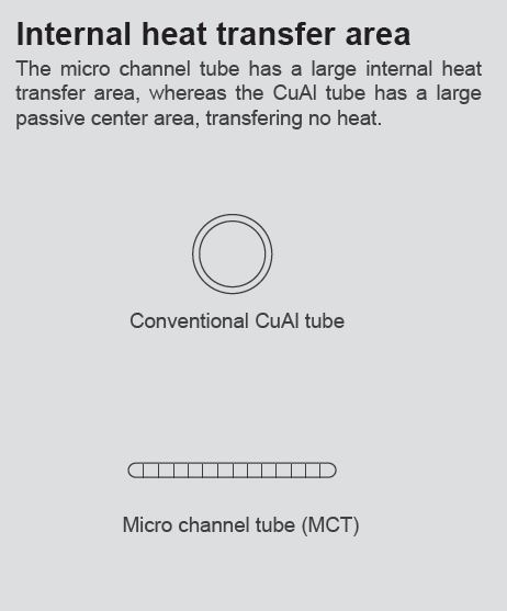
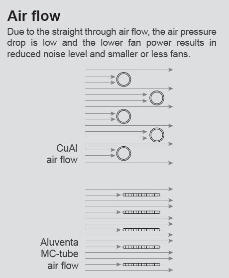
The micro channel tube has several advantages to a round copper tube:
• The internal heat transfer area to flow area ratio is bigger/larger.
• The flow regimes occurring during condensation is more efficient.
• The primary to secondary surface area is bigger/larger.
• The air shadow of the tube is less/smaller.
Basic principle
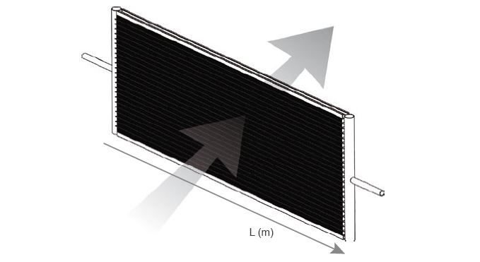
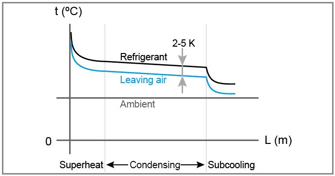
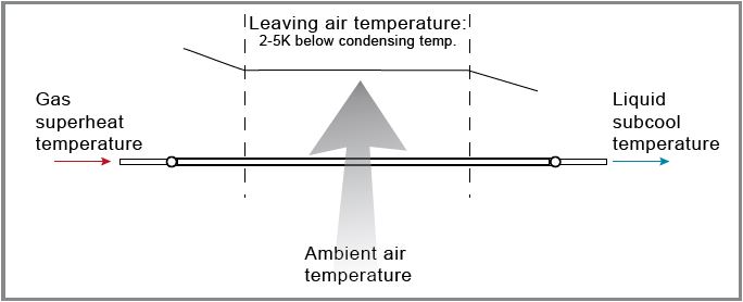
In a single pass condenser the temperature of the leaving air will be high at the beginning of the condenser where the refrigerant is a superheated gas.
Through the middle of the condenser, the temperature of the air will be below condensing temperature,and at the end, where the condensed refrigerant has become a subcooled liquid, the temperature of the air will be low.
This means that the temperature of the mixed air leaving the condenser will be approximately 2-5ºK below condensing temperature.
Coil setup
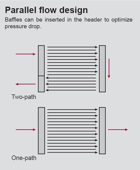
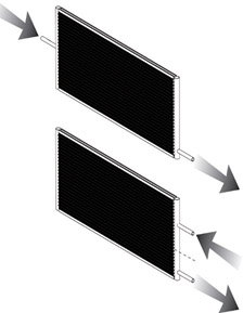
The micro channel coil has low internal pressure drop due to the coil setup with many parallel tubes. The coil can be setup with several pass to optimize the coil for the specific application.
One pass
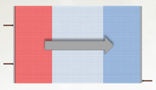
In one-pass setup all tubes are in parallel and this give the advantages of really low internal pressure drop and a good sub-cooling zone. The inlet and outlet connections are placed on opposite manifolds. One-pass setup can be used for all coil sizes and is the recommended setup for coils with length above 2,5-3 meters.
Two pass
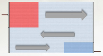
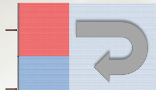
In two-pass setup the coil is splitted into 2 sections and the refrigerant turns around in one of the manifold so that inlet and outlet are located on the same manifold. This give a very compact coil with connection on the same side of the coil and the pressure drop can be reduced based on an optimized splitting between the 2 passes. Two-pass setup can be used for coil with length up to 2,5-3meters.
Three pass
In three-pass setup the coil is splitted into 3 sections and the refrigerant turns around in both manifolds so that inlet and outlet are located on opposite manifolds. This gives a good sub-cooling zone where the pressure drop can be accepted. This setup in mainly used for smaller coils with increased height and reduced lengths.
